
In hot blast furnace, refractory design of hot air duct and steel structure design of tube shell complement each other, and the two are important factors to each other. If the pipe system is unstable, it will cause brick lining dislocation and brick falling, and unreasonable brick lining design will cause cross-wind and damage the tube shell. According to the thermal expansion of the pipeline, the compensation of the pipeline system should be reasonably designed to make the expansion of the pipeline controllable. When designing the brick lining, the refractory material should be reasonably configured according to the temperature gradient in the circumferential direction of the pipeline. The expansion joint should be set in the axial direction of the pipeline, and the refractory structure design of the expansion joint, corrugated compensator, and three-way intersection should be locally specially treated to ensure the sealing performance.
PART.01 Refractory material of hot air duct
The setting of hot air duct compensation requires masonry refractory material in the hot air duct. When considering the compensation of hot air duct, the corrugated compensator can only absorb axial displacement and a small amount of lateral displacement. The pipe system is generally equipped with high-temperature axial corrugated compensators and high-temperature free compound corrugated compensators, and the blind plate force is resisted by setting tie rods. The tie rod will also have a certain temperature rise due to the heat conduction and heat radiation of the tube shell. Under the combined influence of factors such as blind plate force and ambient temperature difference, the tie rod will have a large displacement and fluctuate with the wind temperature, wind pressure, and ambient temperature difference. It is very necessary to consider the displacement and fluctuation of the tie rod in the design.
(1) The hot air outlet is set at the lower part of the burner, and a high-temperature free compound corrugated compensator is set on the hot air branch pipe, which is installed between the hot air outlet and the hot air valve. In this way, the axial expansion of the branch pipe and the lateral displacement caused by the heating of the hot air furnace body can be absorbed;
(2) A secondary fixed support is set at the three-way intersection of each hot air branch pipe and the main pipe, and a set of high-temperature axial corrugated compensators are set between each two fixed supports and at the end of the main pipe, and a full-length large tie rod is set across all hot air branch pipes. In this way, the expansion of the hot air main pipe can be limited between the branch pipes of the two hot air furnaces and the center line of the hot air branch pipe can be fixed at one position. At the same time, the elongation of the tie rod is compensated, and each fixed support is not subject to blind plate force. If the hot air outlet is set at the bottom of the large arch, it is recommended to set the branch pipe tie rod seat to the center of the hot air furnace.
PART.02 Design of refractory structure of hot air duct
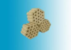
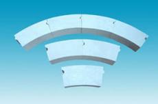
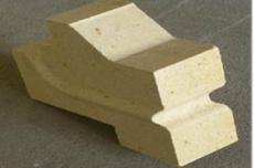
With the continuous increase of hot air pressure and temperature, the requirements for the design of refractory structure of hot air duct are getting higher and higher. The brick lining design should not only consider the integrity of the structure, but also the thermal stress damage caused by the expansion displacement in all directions. The upper working layer of the hot air branch pipe, main pipe and surrounding pipe should adopt a structure with concave and convex grooves to improve the overall stability. The hot air outlet and each three-way intersection should be built with combined bricks, and at the same time, the working layer brick lining should be thickened and the insulation refractory bricks in the upper half of the pipe should be replaced with heavy castables to enhance its stress resistance. The schematic diagram of the thickened structure of the three-way intersection of the hot air main and branch pipes is shown in Figure 2. The working layer refractory bricks and insulation refractory bricks at the corrugated compensator of the hot air duct are all made of special bricks, and diversion protection bricks are added at the expansion joint, as shown in Figure 3. This can enhance the overall stability of the brick lining at the corrugated compensator and effectively prevent the ceramic fiber blanket filled in the expansion joint from being washed away by the airflow. The expansion joint of the hot air duct can refer to the design method of the expansion joint at the corrugated compensator, which has better integrity and can effectively control the width of the expansion joint.
The overall masonry structure of the hot air duct is that the brick lining of the lower 240° area is staggered and padded with ceramic fiber fire baffles; the upper 120° area is ring-laid and padded with ceramic fiber blankets with a temperature resistance of more than 1200℃. The ring joints between the two insulation layer bricks are separated by ceramic fiber paper, and the ring joints between the insulation layer bricks and the working layer bricks are separated by ceramic fiber paper in the lower semicircle and sandwiched with 4~6mm thick ceramic fiber paper in the upper semicircle.
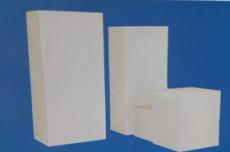
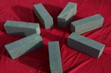
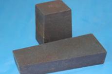
In the selection of refractory materials, it is recommended to use andalusite high-alumina bricks, and the filler at the expansion joint of the hot air duct should be a crystal fiber blanket with a temperature resistance of more than 1400°C, which avoids the failure of the filler in a high temperature environment for a long time and the occurrence of cross-wind.


 HOME
HOME