
Top-fired hot blast furnace
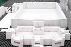
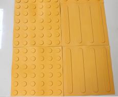
The construction of refractory materials for top-fired hot blast furnace can be mainly divided into four parts, namely labyrinth masonry, air and gas ring masonry, vault straight section and hot air outlet masonry and vault masonry. The main configuration of refractory materials in these four parts can be referred to Figure 1. The specific construction masonry points are as follows:
PART 01 Labyrinth masonry
According to the center elevation of the combustion air pipe, the control elevation of the top of the labyrinth is calculated downward, combined with the relevant dimensions of the drawing, taking into account the actual elevation, horizontality and pre-swing size of the brick support plate installation, determine the thickness of the brick support plate castable leveling layer, and release the labyrinth brick layer control line on the spray layer.
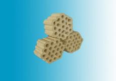
Control the probe size of each layer of labyrinth bricks into the furnace body, pay attention to the joint layer when laying the inner and outer ring bricks of the furnace body, strictly control the sliding joint size (30mm) between the heat storage chamber wall and the labyrinth, and fill with refractory ceramic fiber blanket.
PART 02 Air and gas ring cavity masonry
When laying the first layer of bricks in the air ring cavity, check the seams along the inner ring bricks of the furnace body (to prevent the appearance of processed bricks), ensure that the brick seams are ≤2mm, the inner diameter of the furnace body meets the design requirements (6620mm), and use the radius wheel rod to check whether the arc and the inner diameter of the furnace body are within the allowable range (±15mm). According to the center elevation of the air duct, control the air and gas ring cavity brick layer control line according to 3 layers on the spray layer; the inner and outer ring walls of the air and gas ring cavity should be laid flat, otherwise triangular seams are likely to appear in the over-the-top bricks.
Before laying the entrance of the air and gas pipelines, a δ=3mm stainless steel protective plate needs to be installed, which consists of two halves and is welded to the installation position. Between the gas ring cavity and the air channel, a layer of δ=0.3mm thick 1Cr18Ni9Ti stainless steel sealing plate is vertically laid along the furnace shell; on the air ring cavity over-top brick, two layers of δ=0.3mm thick 1Cr18Ni9Ti stainless steel sealing plates are laid flat with staggered joints. The purpose is to prevent air and gas leakage from causing explosion. The stainless steel plate also plays a sliding role. Therefore, the refractory masonry mortar in this part must be full and have good sealing.
When laying the air and gas ring cavity annular channel, first determine the burner position based on the center angle of the combustion chamber and the design elevation, and then adjust the brick joints (1~3mm) by placing bricks so that the burner nozzle can be evenly arranged along the inner circumference of the furnace body after it is formed. When laying the air and gas ring cavity, first lay the inner ring of the ring cavity, and use a ruler, center wheel rod, etc. to control the verticality, flatness and distance between the walls. The adjacent elevation error of the inner and outer ring walls does not exceed 5mm. If the outer ring wall is 5mm away from the spray coating, fill it with spray coating.
After the burner nozzle is built, the air and gas channels and their annular cavities need to be thoroughly cleaned. After passing the inspection, the burner is sealed and protected to prevent damage and falling debris such as broken bricks.
PART 03 Arch straight section and hot air outlet masonry
Based on the center elevation of the hot air outlet, the brick layer line of the arch straight section is released on the spray layer. During masonry, the elevation and levelness of the lower furnace wall of the hot air outlet (manhole) must be strictly controlled. Within 1m around the hot air outlet and manhole, andalusite bricks are built close to the furnace shell, and the manhole and pipeline are rounded with the help of the center wheel rod and the pipeline radius wheel rod. Pre-set the seam first, and then close the door smoothly. The elevation, flatness and arc of the straight wall under the arch foot brick must be strictly controlled.
During construction, the hot air branch pipe masonry must be arranged in advance so as not to affect the masonry progress of the straight section wall. First, lay the lower semicircle of lightweight clay bricks for the hot air branch pipe. After the radius wheel rod is rounded, lay the second layer of lightweight high-alumina bricks. Set expansion joints according to design requirements. The position and size must be set correctly and the joints must be pressed with andalusite bricks.
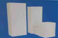
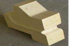
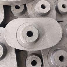
The hot air outlet is built with combined bricks (see Figure 3). The lower straight wall is staggered into the furnace for 4 consecutive layers, with each layer staggered by 34mm. Then, the lower semicircle center wheel rod is supported to control the radius. Petal bricks, outer ring bricks and inner ring bricks are laid in sequence. The upper semicircle is built with inner ring bricks (working layer), outer ring bricks and petal bricks in sequence. Between the hot air branch pipe and the hot air outlet combined bricks, the lower semicircle is poured with steel fiber castables, and then the lower semicircle inner ring bricks are laid. A 50mm expansion joint is designed between the two ring bricks in the upper semicircle and filled with ceramic fiber blankets. The arch is leveled with rigid fiber castables, and two layers of vertical wall bricks (staggered size: 53mm+64mm) are laid in a staggered manner. The center wheel rod of the furnace body is used to find the circle, and the transition section of the cone is filled with thermal insulation castables.
PART 04 Arch masonry
The vertical wall elevation and flatness of the bottom surface of the arch foot brick must meet the design requirements. After the arch foot bricks are placed in a ring and the seams are checked, the position of the arch foot bricks and the gap of the mortar joints are adjusted to ensure that the mortar joints are ≤2mm and the inner diameter requirements are met. The arch foot bricks must be laid close to the furnace shell spray paint.
The arch bricks must be laid according to the brick number ratio. The big head of the brick must point to the furnace. It is strictly forbidden to lay it upside down. The radial joints between bricks must point to the center of the furnace body to avoid staggered or triangular joints; a 5mm expansion joint wooden plywood is placed between every 3 inner ring silicon bricks, and the silicon bricks must be clamped with the expansion joint board for masonry. Since the vault bricks are tilted toward the center of the furnace ring by ring and shrink upward, the inner radius of each ring of bricks should be controlled by the center wheel rod according to the inner radius size of the vault elevation provided by the design (generally the inner radius of the lower opening of the brick layer is given).
Each brick of the vault is placed at an angle and is easy to slide down. The mortar consistency should be increased during masonry. After the mortar is applied to the bricks, it should be put on the wall for a few seconds. At the same time, the silicon bricks should be hooked with brick hooks. The hooks are allowed to be removed only after each ring is closed. As the inner diameter of the vault becomes smaller, the density of the brick hooks should be increased, and each of the last few rings of bricks should be hooked with brick hooks. When laying the vault cover bricks, it is advisable to support the plug-in arch tire under the cover bricks.


 HOME
HOME