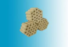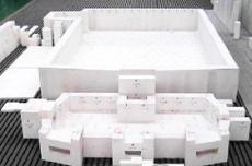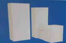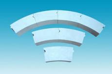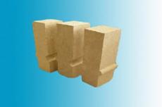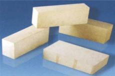
The part below the pit brick
As we all know, carbon roasting furnace is an indispensable thermal equipment in the production process of carbon materials. According to its structure, carbon roasting furnace is divided into two types: closed roasting furnace and open roasting furnace. In the following article, we will share with you the masonry process of refractory bricks for carbon roasting furnace according to its furnace type, furnace body structure, etc. First, start with a closed roasting furnace. The following is the first part of the closed roasting furnace-the masonry process of refractory bricks below the pit brick.
1) Measure the line and set up the pole.
Before bricklaying, the longitudinal and transverse center lines and elevations handed over by the previous process should be re-measured, and the center lines of each roasting chamber should be determined accordingly. The roasting furnace with two rows of roasting chambers is very long, such as the length of a 34-chamber roasting furnace is 100m. Therefore, it is very important to strictly control the center line of each roasting chamber during construction.
On the concrete foundation, draw the edge line of the red brick bottom according to the longitudinal and transverse center lines of the furnace body. Set up wire rods along its outer side. The wire rods are projected with elevations and brick layer lines. The wire rods of the furnace with a fire well should be placed in a position that is convenient for masonry of clay brick furnace walls and fire well walls. The wire rods should be checked regularly to avoid errors.
2) Each brick layer of the furnace bottom.
The masonry of the furnace bottom is composed of red bricks, clay heat-insulating refractory bricks and clay bricks. According to the bottom line of the first layer of red bricks on the wire rod, when the foundation surface is leveled with cement mortar, the reference points can be evenly set to control the elevation and flatness of the plaster layer. When a through expansion joint is left in each brick layer of the furnace bottom, it is advisable to masonry in sections with the joint as the boundary. In order to reduce brick processing, the position of the expansion joint can be moved appropriately. When laying bricks on each layer of the furnace bottom, first lay the bricks on both sides, and then use it as a standard to lay the bricks in the middle with a line to control the flatness of the brick layer surface.
3) Masonry of brick piers.
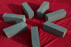
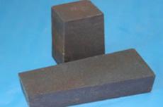
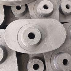
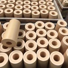
After the furnace bottom is built, the brick piers are built. Each firing chamber has more than 100 brick piers (size: 230mm×230mm×600mm). The space between the brick piers is the passage for smoke. The top of the brick piers is the pit face brick. When laying the brick piers, the design size and elevation should be maintained, especially the size of the channel under the material box wall should be more accurate.
Generally, the surrounding clay brick walls (including the fire well wall if there is a fire well) are built to the elevation of the upper surface of the brick pier, and then the control line is drawn on the wall, and the brick piers are built according to the line. Before laying, the brick piers should be dry-laid so that the top bricks can be staggered with the pit face bricks. The brick piers in the same firing chamber should be strictly kept horizontal. The stagger on the side of the brick pier shall not be greater than 3mm.
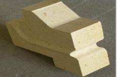
4) Before bricklaying, the selected and combined pit face bricks are dry-laid in the furnace according to the designed position, and the contact surface of each brick is carefully processed to make the dry-laid pit surface stable and the brick seams uniform. When laying bricks, first lay the rectangular bricks of the four frames, and then arrange the square bricks in the middle according to the set juice. After the material box wall is built and cleaned, the mud can be used for formal masonry.
When laying the rectangular bricks of the four frames of the pit surface, the line should be drawn according to the groove on the brick surface to keep the groove in a straight line and parallel and at the same level with the groove on the surrounding walls, so that the position of the first layer of brick grids in the material box is correct and stable. The surface flatness error of the masonry shall not exceed 3mm for the pit surface bricks, and shall not exceed 2mm for the adjacent pit surface bricks under the material box wall.
Masonry of the furnace wall
In a carbon roasting furnace with a fire well, the construction of the clay brick wall and the material box wall can be carried out alternately at the same time. At this time, there is no way to set up the wire pole in the roasting room, and the wire pole on the outside of the original red brick wall must be used for wire pulling work to build the furnace wall. In the entire process of masonry of the furnace wall, the masonry principle of "first lay the horizontal wall, then the two side walls" should be implemented. Therefore, the construction height of the red brick wall cannot exceed that of the clay brick wall.
When building the furnace wall, accurately leave the air duct and gas duct according to the design size and position, pay attention to keep it clean, and the duct should be thoroughly cleaned before switching and closing.
When the furnace wall is built to the burner, its elevation and the distance between the center line of the burner should be strictly controlled. The gas pipe elbow and the masonry should be filled with materials according to the design requirements. The top layer of bricks of the furnace wall should be built sideways.
The masonry system of the connection part between the flue Π-type regulator and the furnace body is an oblique channel, usually called an oblique flue. This part of the masonry has more bricks and a more complex structure. Careful operation should be carried out during masonry.
A layer of isolation steel plate is laid at the contact between the lower masonry of the oblique flue and the arch surface of the collecting flue. Therefore, the arch of the collecting flue should be built first, and after the steel plate is laid, the furnace wall should be built. When the lower corner of the oblique flue is a segmented anti-arch, the triangular masonry between the arch and the anti-arch should be carefully processed.
The top arch of the inclined flue is sometimes built into an inclined arch. The two ends of the inclined arch are connected to the outer wall of the furnace body and the straight wall of the Π-type regulator, and are processed into straight seams. However, the top arch is sometimes formed by a flat arch with 8-10 rings of misalignment. The size of the misalignment should be uniform and the brick ring should be straight.
Masonry of the material box wall and furnace cover
(1) Masonry of the material box wall:
The material box wall is composed of special-shaped bricks with holes. Pre-masonry should be carried out before construction. The selected checkered bricks should be selected, combined, and the matching method should be determined. When laying the first and second layers, dry arrangement should be carried out in the furnace to check the fit between the first layer of bricks and the pit surface bricks, whether the brick layer is flat, and whether there is misalignment between the upper and lower brick holes. The material box wall should generally be built from the middle to the two ends, and finally the four corner bricks should be built. In order to adjust the brick joints, expansion joints and misalignment, the two inclined surfaces of the checkered bricks at the intersection of the material box wall can be processed. The checkered brick masonry requires full mud and grouting of the wall surface.
During masonry, the length and width of the material box should be checked regularly. The length and width errors should generally not exceed ±4mm respectively. At the same time, attention should be paid to the verticality of the material box wall. Each meter should be controlled within 3mm, and the total height should be controlled within 10mm. The center line spacing of the material box should also be checked frequently and should be controlled within.
Expansion joints are generally provided at the intersections and corners of the material box wall. The expansion joints should be uniform and straight, accurate in size, and in accordance with the design, and the corresponding thickness of refractory fiber felt should be filled in the joints.
The scaffolding of the material box wall should generally use special fixed scaffolding to facilitate movement and construction.
