What are the most common regenerative structural forms of domestic sodium silicate melting furnaces?
Sodium silicate, also known as water glass, is widely used in industrial production. As the core equipment for sodium silicate production, the structure of the melting furnace has a crucial impact on production efficiency and energy consumption. Next, let us explore the most common regenerative structure form in domestic sodium silicate melting furnaces!
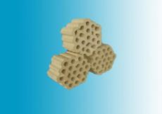
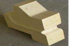
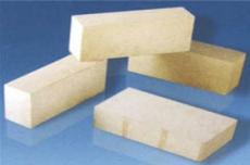
The regenerator, as an efficient waste heat recovery system, plays a vital role in sodium silicate melting furnaces. It uses a special refractory material, checker bricks, as a heat storage body to accurately capture and store the heat energy in the high-temperature flue gas discharged from the furnace. When these high-temperature exhaust gases reach a temperature of 1400~1500°C and flow through the checker bricks in the regenerator, the heat is effectively absorbed and accumulated in the checker bricks, thereby gradually increasing their temperature.
Subsequently, during the flame reversal process, the heat accumulated in the checker bricks is released and used to preheat the gas and air entering the furnace. Through this heat exchange process, the gas can be preheated to 800~1000℃, while the air can reach a preheating temperature of 1000~1200℃. This preheating effect not only ensures that the flame has a high enough temperature to meet the melting conditions of sodium silicate, but also reduces the temperature of the exhaust gas to approximately 600°C when it is discharged from the regenerator, thereby achieving efficient recovery and utilization of heat energy.
In order to further optimize the performance of the regenerator and extend its service life, scientific researchers and engineers continue to explore and innovate. In domestic sodium silicate melting furnaces, there are various designs of regenerators, each of which is designed to improve its thermal efficiency and stability. Among them, connected structure, separated structure, semi-partitioned structure, connected structure with two small furnaces, two-stage structure and fully connected structure are the most common designs. These carefully designed regenerator structures not only improve the recovery rate of heat energy, but also provide a strong guarantee for the energy saving and efficient operation of the sodium silicate melting furnace.
PART.01 Connected structure
One of the design concepts of the sodium silicate melting furnace is to design the air regenerator and gas regenerator under the small furnace on one side into a connected single-chamber structure. The original intention of this design may be to simplify the structure and facilitate airflow. However, in practical applications, we found that this connected design has obvious disadvantages.
The main problem is that the airflow is difficult to distribute evenly in the connected room. Due to the lack of effective airflow separation and guidance mechanisms, the airflow can easily form vortices or short circuits in certain areas, resulting in excessive airflow speeds and excessively high temperatures in local areas. This local overheating phenomenon will accelerate the thermal deterioration and damage of the checker bricks, seriously affecting the service life and performance of the regenerator.
Therefore, although this type of connected regenerator design is relatively simple in structure, it has been gradually eliminated in practical applications due to its uneven air flow distribution and the tendency to cause local overheating. We prefer to adopt more advanced designs with more uniform air flow distribution to ensure stable operation and efficient energy consumption of sodium silicate melting furnaces.
PART.02 Separated structure
The design of the regenerator on one side of the sodium silicate furnace is quite ingenious. It adopts a partitioned design based on each small furnace, forming several independent chambers that are not connected to each other. The subtlety of this design is that it allows precise adjustment of gas distribution through the gates on each branch flue, thereby achieving effective communication with the gas and air branch flues.
From a professional point of view, the significant advantages of this structure are the flexibility and precision of gas distribution. By simply adjusting the gate, operators can easily control the gas flow in each individual chamber to meet the needs of different melting stages. In addition, the design also provides convenience for hot repairs, as the construction of independent chambers makes local repairs possible without shutting down the furnace or affecting the normal operation of other areas.
However, this compartmentalized design also has certain limitations. Although the setting of the dividing wall achieves independent distribution of gas, it also takes up part of the space, resulting in a reduction in the effective volume of the grid. This means that within the same space, the heat storage capacity of the grid may be affected to a certain extent.
Nonetheless, this regenerator design was widely adopted due to its flexibility and serviceability, becoming one of the most common structures in sodium silicate furnaces. In actual operation, through reasonable gas distribution and optimal configuration of the grid, its effectiveness can be maximized to ensure efficient and stable operation of the furnace.
PART.03 Semi-divided structure
The semi-partitioned structure is unique in the design of sodium silicate furnace regenerators. Specifically, this structure separates each small furnace in the flue section above the grate. This design not only retains the independence of each small furnace, but also allows flexible adjustment when necessary. Gas distribution adjustment.
It is worth noting that the regenerator itself is not completely separated, or is only separated to a certain extent in the lower part, while the upper part remains connected. This design takes into account both the uniformity of gas flow and the convenience of operation and maintenance. In actual operation, the adjusting gate for gas distribution is still set on the branch flue, so that the gas flow of each small furnace can be precisely controlled by adjusting the gate to meet different needs in the smelting process.
From a professional point of view, the semi-divided structure retains the advantages of the divided design while avoiding the possible problems of space occupation and reduction of the effective volume of the grid. In addition, the structure retains the integrity of the connected design, allowing for more uniform gas flow and reducing the risk of local overheating and damage to the checker bricks.
PART.04 Connected structure of two small furnaces
The two-small furnace connected structure is an innovative design of the sodium silicate melting furnace regenerator, which merges two adjacent small furnaces into one chamber, and each small furnace is equipped with an independent branch flue for gas distribution. Fine tune. Compared with a completely separated structure, this design significantly reduces the use of partition walls, thereby increasing the heat exchange area of the lattice body and effectively improving thermal efficiency.
However, the implementation of this structure also comes with some technical challenges. Due to the reduction in the number of partition walls, the stability of the side walls will be affected to a certain extent, requiring careful consideration in structural design and material selection to ensure safety. In addition, although the two-to-two connection feature optimizes heat distribution, it brings certain operational difficulties during hot repair. Because the connected nature means that two small furnaces need to be processed at the same time during maintenance, this undoubtedly increases the complexity of maintenance and the impact on the production process.
PART.05 Two-stage structure
The two-stage structure shows a unique idea in the design of the sodium silicate melting furnace regenerator. The structure cleverly divides a single regenerator into two independent parts, separated by partition walls and connected by a vertical channel. This layout allows the regenerator to be clearly divided into high-temperature and low-temperature zones, with each zone undertaking different heat exchange tasks.
The original intention of adopting a two-stage structure is mainly to solve the problem of sodium sulfate's erosion of checker bricks during the conversion process of gas, liquid and solid. By limiting this transformation process to the connecting channels, the structure effectively extends the service life of the checker bricks and improves the durability and stability of the furnace.
However, although the two-section structure has significant advantages in protecting the checker bricks, it is rarely used in modern furnace designs due to its relatively complex structure, which increases the difficulty of construction and maintenance. Despite this, this classic design still provided valuable inspiration and reference for subsequent technological improvements.
PART.06 Fully connected structure
The fully connected structure is a unique and efficient solution in the design of sodium silicate furnace regenerator. By connecting the entire regenerator into a large space, this structure maximizes the heat exchange area of the lattice body, thereby significantly improving thermal efficiency. This design is similar to a large heat exchange network, in which each small furnace is connected to this network through its own branch flue, achieving precise control of the gas distribution of each small furnace.
However, the implementation of this structure is not without challenges. Due to the lack of partition walls, the stability of the side walls became an issue that required special attention. In order to make up for this shortcoming, engineers need to carry out careful planning and strict execution in material selection, structural design and construction technology.
In addition, the fully connected structure also has certain maintenance difficulties. Once local checker bricks collapse or are blocked, local hot repair operations cannot be performed because the entire regenerator is connected. This requires that possible failure situations need to be fully considered during the design stage and corresponding preventive measures and emergency plans need to be formulated.
Despite this, the fully connected regenerator is still widely used in fields such as large float glass melting furnaces due to its efficient heat exchange performance and flexible gas distribution. This design not only improves energy efficiency, but also makes important contributions to the stable operation of the furnace and energy conservation and emission reduction.
