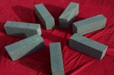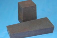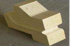
The melting section of the glass melting furnace is located above the liquid glass level. The entire space of the furnace filled with flame and surrounded by the front wall (L-shaped hanging wall), retaining wall, large arch and rear gable is called the upper structure of the melting section, also known as the flame space. This space is not only a space for the combustion of the flame, but also a heat transfer space where the flame gas transfers its heat to the glass liquid, retaining wall and roof. The size of the flame space depends on the scale of the furnace, the type of fuel and the amount of fuel consumed. The larger the melting volume, the greater the total fuel consumption, the larger the space required for combustion, and the larger the size of the flame space. When using fuel oil as fuel, since the combustion of fuel oil in the furnace is different from that of coal gas, the processes of fuel oil atomization, oil droplet evaporation, thermal decomposition, diffusion, mixing and combustion occur in the flame space. Therefore, there must be enough combustion space to ensure complete combustion of oil mist. Therefore, from the combustion point of view, the flame space of the fuel oil furnace is slightly larger than that of the gas furnace. For the smelting furnace that also uses fuel oil, the fuel oil atomizer is inserted into the plane of the pool wall. Since the nozzle brick raises the fire outlet of the small furnace, its combustion space is larger than the space of the heavy fuel atomizer inserted into the lower or upper layer of the small furnace. However, from the energy saving point of view, it is better to insert the heavy fuel atomizer into the lower or upper part of the small furnace than to insert it flat on the pool wall. The width of the flame space is generally larger than the width of the furnace bath, 250-300 mm on each side. Since the inner side of the furnace bath bricks is easily corroded and damaged after the melting furnace is put into operation, the retaining wall is built closer to the outside in order to protect the retaining wall and prevent the cast iron parts from burning. The height of the fire space is equal to the height of the retaining wall plus the height of the support. The size of the flame space should correspond to the space required for fuel combustion. Therefore, the height of the flame space mainly determines the type and amount of fuel used in the furnace. At the same time, it is necessary to consider the reduction in heat transfer of the furnace and the stability of the furnace roof. After the transition from gas to fuel oil and from the small furnace to the plug-type furnace, the height of the retaining wall was increased, but the flame space could not be too large, otherwise it would increase the heat dissipation of the furnace body and increase the waste space inside the furnace body, making the flame soft and floating, which would not be conducive to heat transfer in the furnace. Therefore, on the premise of ensuring the cross-sectional area of the nozzle and the stability of the roof, the height of the flame space tends to be lower to facilitate the heat transfer from the flame and roof to the batch and molten glass and reduce the heat loss of the furnace body to the outside.
01 Structure of the Front Wall
The front wall or L-shaped suspended wall is the front end wall of the flame space of the melting section. Together with the large arch, it forms the front space of the melting department. Its main function is to block the hot air flow from the front feed point of the melting furnace to save fuel; and reduce the heat radiation of high temperature to the feeder and the silo of the furnace head. At present, L-shaped suspended walls are most often used as facade walls. They are not only structurally sound and do not require thermal repair, but also have much greater thermal strength than facade walls with arches and flat suspended walls as the main structure. The L-shaped suspended wall is composed of two parts of steel and brick structure. The lower structure (commonly called the nose area) has several shapes, including 45°, 30° and 60° (the angle between the inclination of the nose area and the horizontal plane). The most commonly used is the 45° air-cooled column curtain wall. The nose of the L curtain wall adopts zirconium composite bricks, which consists of 33# oxidation non-shrinkage fused zirconium corundum bricks and sintered zirconium mullite embedment bricks. Due to the low temperature, sintered zirconium corundum bricks are still used in the lower part of the nose; High-quality sand-lime bricks are used in the straight section, and a layer with baked zirconium bricks. Different kinds of bricks are laid on the refractory mortar, suspended on the heat-resistant steel castings by special hooks. In the production process, after the cooling air enters the air box truss, it is discharged into several vertical pipes of the air column, and the heat-resistant steel claw hooks are also fixed to the pipes, and the air flow directly cools the claw hooks. In normal production, the wind pressure in the cavity consisting of the steel structure of the hanging wall and the brick structure should be 40-60 Pa higher than the melting furnace pressure, the temperature should not exceed 110 °C, and the maximum instantaneous temperature should not exceed 160 °C. In order to facilitate the control of the wind pressure and temperature, only a fan is generally used for adjustment. The short wall at the junction of the upper part of the aft pool wall on both sides of the bow of the L-shaped hanging wall and the retaining wall of the melting part is called the wing wall. The wing wall is generally built by the oxidation method of 33# ordinary fused zirconia corundum casting bricks and high-purity resistant zirconia bricks. Its main function is to compensate for the places where the overhanging wall cannot be sealed; The upper part of the L-shaped suspended wall and the junction of the melting part are lined with high-quality sand-lime bricks; the outer part of the suspended wall is insulated with calcium silicate board, and then the 1.5-3mm thick galvanized sheet is used as the protective sealing plate. Since the lower part of the L-shaped suspended wall cannot completely block the flame in the furnace, the front water bag or suspended wall is used to block the area in front of the nose of the L-shaped suspended wall near the batch material.
02Retaining wall structure
The retaining wall is supported by the I-section columns on both sides of the smelting furnace, and is mainly composed of chin iron, retaining wall base plate, hook bricks and retaining wall bricks. The retaining wall needs to ensure sufficient structural strength under high temperature, and the hook brick is the key element. Its function is to protect the chest wall base plate, the bottom of the chin and other parts of the iron. Some hook bricks of the smelting furnace are protected by bottom gap bricks and small bricks. The retaining wall of the smelting room is generally built of zirconium corundum bricks, the retaining wall of the clarifying room and the retaining wall of the cooling room are generally built of sand-lime bricks, and the joints between the zirconium corundum bricks and the sand-lime bricks are covered with zirconium bricks. The thickness of the retaining wall is generally 400mm-500mm, mainly to reduce heat loss. The height of the retaining wall and the large arch together constitute the height of the fire space. Therefore, the height of the retaining wall is also related to the size of the flame space and the amount of heat dissipated from the furnace body. The height of the retaining wall varies according to the fuel used and the corresponding height of the outlet of the small furnace. Generally, the height of the retaining wall of the float glass production line is 1400mm-1700mm. The force transmission path of the retaining wall: retaining wall weight → hook brick → retaining wall base plate → chin beam → steel column - furnace hearth secondary beam → furnace hearth main beam → furnace hearth concrete column. The retaining wall of the smelting section adopts 30mm thick zirconium sealing material and 65mm thick lightweight high-alumina bricks for cold insulation from the inside to the outside; The retaining wall of the clarifying section adopts 80-140mm thick lightweight insulation coating for thermal insulation from the inside to the outside.
03 Large arch structure
The arch, like the retaining wall, is supported by I-beam columns on both sides of the smelting furnace. It is mainly composed of steel arch ballast, side arch bricks, arch bricks and tie rods. Since the smelting section is in the high temperature zone of the entire furnace, in order to ensure the safety of the steel slag in the smelting section, the steel slag in the smelting section needs to be air-cooled while the steel slag in the clarifying section is not cooled. The function of the large arch: It forms a flame combustion space with the retaining wall, and can also serve as a medium for radiant heat transfer from the flame to the batch and glass liquid, that is, it absorbs heat during fuel combustion and then radiates it to the liquid surface. In terms of heat radiation and dissipation, the closer the crown is to the liquid surface, the more radiant heat is reflected to the glass and the less heat is dissipated. Therefore, the crown should be lowered as much as possible while ensuring its structural strength. The main way to lower it is to make the crown smaller. Selection of arch bricks: Since the arch of the melting part is exposed to high temperature, the arches using air combustion are all made of heat-resistant high-quality sand-lime bricks (the melting window of the full oxygen combustion uses 33# zirconium corundum bricks or α-β corundum bricks). The length of a large arch brick is usually 350 mm, for arches with a span of more than 10 m, a brick of 450 mm in length is used, and for special load-bearing arches, a brick of 500 mm in length can be used. The arch is divided into several masonry sections, each of which is independent, and an expansion joint is left between two sections of the arch to compensate for the expanding properties of sand-lime bricks during ignition and firing of the kiln. In cold repair, the most severely burnt section or two sections can be removed without replacing the entire arch. Strict quality requirements are imposed on the masonry, and the joints must be small. The inner surface of the sand-lime brick arch can be flat or cellular. The thermal radiation coefficient of an arch made of cellular ballast brick is 15% higher than that of a flat one. However, the production cost of cellular sand-lime bricks is relatively high, so they are less commonly used at present. Crown and span: From the point of view of thermal engineering, a lower crown is advantageous because it can distribute the thermal radiation as evenly as possible over the entire transverse surface and reflect more radiation energy into the glass liquid. There are two ways to lower the height of the crown: one is to reduce the height of the retaining wall, and the other is to reduce the reserve of the crown. However, there is a limit to reducing the height of the retaining wall, and when lowering the furnace crown, the strength of the structure must also be taken into account. Since the furnace crown has a lateral thrust force, this force will be greater at high temperatures.
If the tie rods are too loose or too tight, or the tension is uneven, the crown structure will weaken and the top will crack or sag. The thinner the roller strands, the greater the lateral draft. Therefore, the only way to minimize the flange is to ensure sufficient structural strength, the functionality of the steel structure, and a certain amount of flame space. The force transmission path of the large arch: the weight of the large arch → steel ballast of the arch → upper support plate → steel column → secondary beam of the furnace hearth → main beam of the furnace hearth → concrete column of the furnace hearth. The bases of the steel columns on both sides of the arch are fixed to the secondary beams, and the column heads are tied with ties on the top of the arch to support the horizontal load of the arch. The retaining wall, arch and furnace basin are divided into three independent supporting parts, and the load is ultimately transmitted to the steel structure at the bottom of the furnace. The retaining wall of the melting room and the big roof are sealed with side arch bricks (the upper gap bricks were used previously), and the retaining wall of the clarifying room and the big roof are sealed with upper gap bricks to protect the steel ballast of the big roof from being burned by flame and radiant heat. In some melting furnaces, the hook bricks are protected by the lower gap bricks between the retaining wall and the furnace basin, and a row of electric-melted head bricks are laid on the lower gap bricks to protect the hook bricks and iron parts. Insulation of big roller: Since the big roller is the main heat dissipation member of the melting furnace, in order to save energy and reduce energy consumption, it is necessary to insulate the big roller when necessary. Due to the different understanding of insulation materials and insulation technologies, different companies adopt different insulation procedures. Typical method: After cleaning the outer surface of the arch, apply a 5mm thick layer of silicate slurry on it one by one to ensure the complete sealing of the brick surface → apply 30-50mm thick silicate sealant → dry lay 2-3 layers of 65mm thick lightweight silicate bricks → apply 50-60mm thick silicate plastic → apply 80-100mm thick lightweight thermal insulation coating → apply 40-50mm thick lightweight high-strength thermal insulation coating as a protective layer. The use of insulation can not only greatly reduce the surface temperature of the arch, thereby reducing heat dissipation and saving energy, but more importantly, it can reduce the temperature gradient inside and outside the arch bricks, increase the temperature of the inner surface of the bricks, and improve the heat transfer of the arch to the liquid glass, so that the batch melts faster, becomes more transparent, and the quality of the glass is improved.
04 Corrugated structure
Anti-corrugated structure is mainly used in producer gas-fired smelting furnaces. In plate glass melting furnaces operated with produced gas, anti-corrugated structure is adopted at the junction of the small furnace outlet and the large roof. The function of the anti-corrugated structure is to transfer the weight of the large dome located at the top of the outlet of the small furnace to the slag in the large dome on both sides of the outlet through the anti-corrugated structure perpendicular to the direction of the large dome, and then to be supported by the columns on both sides of the blast furnace. This design can significantly reduce the height of the horizontal wall of the combustion furnace and reduce the heat loss due to dissipation. When the anti-corrugated design is not used, the small furnace outlet is located under the large slag dome, providing a higher wall and a larger heat dissipation area. There are no iron parts at the connection part of the outlet and the breakwater large crown, so there is no risk of damaging the steel structure. The large crown also contains anti-corrugated material and slag. No expansion cracks were found in the anti-corrugated part and slag. The requirements for the quality of the masonry are very strict. To ensure sufficient structural strength and water resistance, the bricks must be pretreated and numbered. The anti-wavy and large crown are made of high-quality sand-lime bricks. The anti-wavy bricks should be built of cinder bricks with large and small butts on all four sides so that they can cover the arches in the large crest direction and the arches in the wave-resistant direction (there are also six sides). For the same nozzle width, the anti-wavy section is larger, and the anti-wavy slag is protected by a small furnace chimney and is not burned. However, if the span is too large, the strength of the structure will decrease. This design limits the increase in the nozzle width.
05 Front Rear
The rear gable is a wall at the end of the casting section, built directly above the low crown (also called the support crown). Its main function is to block and seal the air flow. The rest of the wall is built of high-quality sand-lime bricks, except for the inspection hole and camera hole, which are made of durable zirconium bricks. In some production lines, the melting and cooling sections of the furnace use "J" or "U" shaped double hanging walls instead of the usual rear gables to effectively block the air flow, but the structure is complicated and requires a large investment.
